 Graphic Design Courses
It’s sometimes helpful when drawing to set up an Autocad 2d grid, for example, if you were drawing support beams evenly spaced on a floor plan. Or, as in the screenshot below, if you were creating a diagram of a circuit board with equally spaced tracks and connectors. As you draw, the cross hairs of your cursor will jump to points defined by a rectangular grid. In this way your cursor movement is restricted to specified intervals of say 5 metres or of 10mm in both X and Y directions, or at an aspect ratio which gives different spacing along the axes, eg. 10mm along the X axis and 15 along the Y axis. Setting up a grid to assist in drawing is one of the many features we explore in our Autocad 2d courses.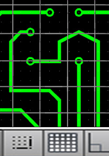
You can also choose an isometric or a polar format for your grid. When the Snap function (F9) is on, the geometry you draw is locked into alignment with the snap points. The array of snap points will be invisible until the Grid (F7 or Control+G) command is activated. In older versions of the program the grid is displayed as a series of dots, but from Autocad 2013 onwards it’s shown as a grid of light grey lines. It functions just the same though.
To access the settings for both Snap and Grid right-click on either button on your bottom Status bar, or type grid in the Command line. Note that this grid is used only for visual reference; it will not be printed.
The Grid array can equal the Snap array or it can have a different spacing and aspect ratio to that of the Snap. A value of zero sets the grid spacing to be equal to that of the snap spacing. If you can’t see the full grid, zoom in, double-click the mouse-wheel and pan across to make it visible.
More information on all features of Autocad can be found at the AutoDesk website. And see many examples of our clients’ work on our Facebook page.
Other related Autocad 2d Blog Posts:
Autocad 2d grid
Feb7
